Rabu, 10 November 2010

VIDEO CAMERA EXPERIMENT

A. Goal

1. Know the video camera.
2. Measuring the composite video on a video camera.
3. Determine the parameters of composite video.

B. Used Equipment
1
Video Camera
1 Oscilloscope 40 MHz and passive probe
An RCA cable connector - BNC (75
W )

C. Circuit diagram

D. Basic Theory

A video camera is a camera used for electronic motion picture acquisition, initially developed by the television industry but now common in other applications as well. The earliest video cameras were those of John Logie Baird, based on the electromechanical Nipkow disk and used by the BBC in experimental broadcasts through the 1930s. All-electronic designs based on the cathode ray tube, such as Vladimir Zworykin's Iconoscope and Philo T. Farnsworth's Image dissector, supplanted the Baird system by the 1940s and remained in wide use until the 1980s, when cameras based on solid-state image sensors such as CCDs (and later CMOS active pixel sensors) eliminated common problems with tube technologies such as burn-in and made digital video workflow practical.

A typical analog camcorder contains two basic parts:

  • A camera section, consisting of a CCD, lens and motors to handle the zoom, focus and aperture
  • A VCR section, in which a typical TV VCR is shrunk down to fit in a much smaller space.

The camera component's function is to receive visual information and interpret it as an electronic video signal. The VCR component is exactly like the VCR connected to your television: It receives an electronic video signal and records it on video tape as magnetic patterns. These two sections are easily seen in the following photos.

A third component, the viewfinder, receives the video image as well, so you can see what you're shooting. Viewfinders are actually small, black-and-white or color televisions, but many modern camcorders also have larger full-color LCD screens. There are many formats for analog camcorders, and many extra features, but this is the basic design of most all of them. The main variable is what kind of storage tape they use.

Digital camcorders have all these same elements, but have an added component that takes the analog information the camera gathers and translates it to bytes of data. Instead of storing the video signal as a continuous track of magnetic patterns, it records the picture and sound as 1s and 0s. Digital camcorders are so popular because you can copy 1s and 0s very easily without losing any of the information you've recorded. Analog information, on the other hand, "fades" with each copy -- the copying process doesn't reproduce the original signal exactly. Video information in digital form can also be loaded onto computers, where you can edit it, copy it, e-mail it and manipulate it.

In the next section, we'll look at the heart of the camcorder, the semiconductor device that converts visual information into an electronic signal.

A comprehensive idea of a TV camera function is depicted in Figure 3-2 and 3-3. In Figure 3-2 the camera is aimed at scene / view so that the optical image can be focused on the target plate tube makers (pick-up tube). If you can look inside, you'll see the shadow-optical. The resulting video signal is shown by the oscilloscope waveform in the bottom left of the picture. Above is a monitor oscilloscope, which shows a reproduced image.

Figure 3-3. Block diagram that shows how the television camera composite video signal output channel. Here is shown the reflection and focusing the camera tube.

Details of the video signal waveform which is more fully shown by the block diagram in Figure 3-3. At first, blanking pulses added to signal the camera. They cause the signal amplitude to the black levels so retrace the MRV will not be visible. Further alignment pulses (sync) is inserted. Alignment (synchronization) is required to set the time & MRV horizontal and vertical.

Alignment (synchronization) is required to set the time & MRV horizontal and vertical.
Camera signal with blanking and
synchronization (sync) is called a composite video signal (composite video signal). Sometimes the term is not a composite video signal (noncompoxite video signal) is used to identify the signal with blanking camera but without alignment. Standard output level of the composite video signal from the camera is 1Vpuncak-to-peak (pp = peak to peak) with the alignment pulses in the down position for negative polarity.

E. Experimental Procedure
1. Set-up devices like the picture above, connect the video camera out with input
CRO.
2. Consolidate his instrument.
3. Set the appropriate CRO to be easily observed (MODE on the TV-H position and / or TV-V). When seeing a wave of horizontal synchronization MODE switch put on the TV-H position, while to see a wave of vertical sync put the MODE switch on the
TV-V position.
4. Determine the synchronization pulses, blanking pulses, front and rear porch, and image information.
5. Image of the wave form and specify
voltage.

F. Experiment Results and Analysis

Data Analysis

G. Conclusion

1. Blanking pulse causes the signal amplitude to the black levels so pengulangjejakan (retrace) the MRV will not be visible.
2. Toll-alignment (synchronization) is required to set the time & MRV horizontal and vertical.
3. Voltage is obtained between the mode switch on the TV-V = 1.2V while the mode switch on the TV-H = 2 V.
4. Alignment between the scanning process on the camera with a TV is called synchronization.
5. The components forming the composite video is 5, namely:
• image signal (luminance signal)
• horizontal blanking pulse
• vertical blanking pulse
• Horizontal synchronization pulse
• Vertical synchronization pulse

Kamis, 28 Oktober 2010

PATTERN GENERATOR

Experimental Purposes
1 Getting to know the basic Pattern in the pattern generator.
2 Measuring standard composite video and Voltage on each Pattern.
3 Measuring the modulated wave on the video modulator.
4 Measuring IF video.

Circuit diagram


Tools and materials in used
A Pattern Generator signal TV, LODESTAR CPG-136 74
An Oscilloscope 40 MHz
A Passive Probe
A Power Supply
A BNC to BNC 75Ω cable
A BNC to RCA 75Ω
A T connector

Experimental Procedure
1. Set-up equipment look like in the circuit diagram
2. Connect the Pattern Generator with power source 8, 5 V, and then push ON the instrument.
3. Pattern generator output switches on and observe put on VIDEO waveforms for each pattern.
4. Observe and picture synchronizing signal and horizontal blanking, vertical blanking, front and rear porch, and image information of each pattern
5. Images and specify voltage waveforms.
6. Pattern generator output switches on and observe put in the IF waveform for each pattern and frequency measurement.
7. Image of the wave form and specify voltage.
8. Image signal for one frame (still image) in composite video, determine the level and period.


Basic Theory

CPG1367A is designed for repairing and adjusting any defect on TV set in PAL system. The RF rang is covering from VHF CH3‐CH4 and including color pattern, white raster and for basic patterns. The unit is used of IC circuit, air variable capacitor inner tuner and crystal controlled progressive scanning circuit. Such design for of cute and portable type is really an efficient instrument for TV set servicing industry.
Features of
CPG1367A:
-The employment of IC achieves high stability and accuracy.
- Color pattern for testing PAL system TV color circuit.
- Four basic pattern as dots, square‐crosshatch, vertical lines and horizontal lines for testing and adjusting most of TV circuits.
- White resters pattern is used for testing purity and white balance.
- Battery or AC adapter operation.
Specifications
of CPG1367A:


A Pattern Generator or Generator Digital Pattern is an electronic testing equipment or software used to generate the stimulation of a digital electronics. Digital electronic stimulation of certain types of electrical wave form varies between two voltages that match the conventional two-logic ('logic low' and 'logic high' or '0 'and the '1'). The main purpose of the digital pattern generator is to stimulate the input of digital electronic devices. A digital pattern generator is a synchronous digital stimulus sources, a pulse generator has the objective to generate electrical pulses of various shapes, they are mostly used for testing in the field of electric or analog.
Various kinds of image patterns in the Pattern Generator are as follows:
a. Dot
To check and adjust the static convergence in the middle of the screen with a low brightness. This should be done according to the television manufacturer's instructions.

b. Crosshatch
Plaid pattern with horizontal lines and vertical lines with the background color of black and white color line.
1) To check and adjust the horizontal and vertical dynamic convergence and the convergence angle.
2) By linearity of deflection the correct horizontal and vertical, horizontal white lines should be a rectangular equilateral.
If this line is not sharp and visible lower intensity than the horizontal line, the amplitude response is possible recipients will not be enough.

c. White

This pattern contains a signal 100% white (without color information) with alternating burst.
1. Images for constant brightness on the entire screen
2. Color picture tube for setting a good white
3. Limitation of fire flow on the color picture tube.
4. For the video recorder is ideal pattern for the current settings. It can also to set the FM demodulator (setting white level).

d. Color

Color beam consists of 8 vertical color bar standard and a reference beam horizontally. Beams 8 colors are arranged in order of depreciation luminance. From left to right beams D color is white, yellow, cyan, green, magenta, red, blue, and black. This pattern is used to set the operational control of the receiver at the correct position. Horizontal beam (white level) on the bottom of this pattern is used as a standard when set the amplitude of color differences in correlation with luminance signal in the picture tube. Signals can be used for resetting the signal amplitude of the demodulator circuit and the matrix, as the output can be compared with the reference beam. In addition to the above purposes, this pattern can be used to check the overall color appearance. So can also be used checks and settings on the receiver or VCR:
1. Lock Inspection burst.
2. AGC examination of color and which create the color.
3. Examination series reactance of the subcarrier regenerator.
4. Examination of the regenerator subcarrier synchronization.
5. Checking circuit identifier (identification) PAL.
Signal Synchronization
Synchronization signal is a signal that is always given periodically and remains, serves to drive a raster scanning path in every television set so that the formation of the video signal into an image and the exact arrangement will remain the same as the original position in the field of raste camera (picture production), therefore the synchronization signal is always supplied along with the video signal sent anywhere. For the formation of this raster scanning system will require two kinds of synchronization are:
- Namely the horizontal synchronization signal to the horizontal scanning provided at each horizontal retrace.
- Vertical sync signal is for vertical scanning provided on each vertical retrace.

Video signal which is equipped with synchronization signals called the complete video signal (Composite Video signal / CVSl), while for color video signal is called Color Composite Video Signal (CCVS). Because the video signal has been added color information signals, i.e. signals and signal Burst Color Sub Carrier.


Result

PATTERN
VIDEO
IF
Vpp
Period
Vpp
Dot
0.29 Vpp
6.2µs
0.12Vpp
Cross Hatch
0.3 Vpp
6.2 µs
0.12 Vpp
Vertical Lines
0.28 Vpp
6.2 µs
0.12 Vpp
Horizontal Lines
0.29 Vpp
3.1 µs
0.12 Vpp
Raster
1.2 Vpp
1.7 µs
0.05 Vpp
Color
2.2 Vpp
1.8 µs
0.1 Vpp


CONCLUSION

1. Voltage at all about the same video system.
2. At the time of the IF mode is turned down because the amplitude of the voltage will also be down
3. IF output frequency is also almost the same because there is no significant difference in amplitude.
4. Tension on the composite video is lower than the voltage on any other video system


Jumat, 08 Oktober 2010

VIDEO MODULATOR

Objectives:

1.Measuring the frequency spectrum of video transmission.

2.Determine the image carrier frequency range and sound carrier frequency.

3.Specifies the bandwidth on video transmission.

4.Specify the type of modulation on the picture and sound


Equipment Used:

1 Video modulator (VCD / VTR / video sender).

1 Spectrum Analyzer.

1 cable connector RCA- BNC.


Circuit diagram:

Introduction:

How to transmit image signal which the amplitude is modulated similar to a radio broadcasting system that has been known.
In both cases, the amplitude of a carrier wave radio frequency (RF) is made varies with the modulating voltage. The modulation is a signal of fundamental frequency (baseband).
On television, this baseband signal is a composite video signal. Television broadcast is similar to a radio system, but includes pictures and sound.
Sound signal emitted by joining it in frequency modulation (FM) on a separate carrier wave transmitter in the same channel as the image signal.

This image signal means a modulated carrier wave.
The video signal is a signal for a picture tube. Video signal for the television audio is correspond to the sound system signal. Details for the AM image signal (amplitude modulation picture) and an FM voice signal.


Figure 2.a shows the frequency spectrum of video transmission that produces an image signal comprising AM picture carrier frequency (center frequency) and sound carrier frequencies (frequency side of the upper and lower side frequencies) - without VSB, while Figure 2b shows the frequency spectrum in transmission generate video image signals of AM frequencies only have the upper side only (with VSB).

A variation of DSB is used for broadcast TV. Under the FCC requirements, the standard video signal occupies a bandwidth of 4.5 MHz. The sound signal is separate and is transmitted at the upper edge of this signal. When carrier is shifted to bandpass, this one sided bandwidth becomes 9 MHz. This is nearly ten times as large as the total bandwidth occupied by all the channels of the AM radio. Use of SSB modulation would cut this in half but SSB is not used for video signals because of the complexity of the SSB receivers. TV manufacturers particularly American companies were instrumental in setting these standards like to keep the cost of the TV’s as low as possible so SSB receivers are not used.

This filter takes in a small part of the upper edge of the lower sideband, starting from -1.25 MHz. The signal is attenuated in this range from -1.25 MHz to -.75 MHz. From here on to 4 MHz, the signal is transmitted full strength. At 4 MHz it is once again attenuated down to 4.5 MHz so as not to interfere with the sound carrier which is demodulated separately. The shaded portion is what is transmitted.

The term vestigial is used since a tiny trace part of the lower sideband is also included in the transmission. The net result is that instead of transmitting a 9 MHz signal, we transmit only 6 MHz, the standard video signal today.

Unlike voice signals which have no components near the zero frequency, Video signals are very sensitive to their low frequency content. Distortion in these components degrades the picture. So extra care has to be taken to make sure that all the low frequency components (which are located in the center) are transmitted without distortion. VSB modulation transmits these low frequencies at the twice level. The motivation for filtering the signal in this way also comes from the desire to use a diode demodulator which requires an explicit carrier. But to recover the carrier we need to go a little to the other side of the carrier frequency and take in an attenuated part of the signal because of the limitations of practical filters. The development of this filter was a function of a compromise between bandwidth and the TV receiver complexity.

The new HDTV standard is also based on VSB.


Lecture Video for Amplitude Modulation:


Experimental Procedure:

1.Calibrate the Spectrum Analyzer by determine the reference spectrum.

2.Set-up instruments just like in the picture above.

3.Turn ON the instrument.

4.Measure the video modulator output (RF) using the Spectrum Analyzer and observe the frequency spectrum.

5.Draw the frequency spectrum.

6.Determine how much is the images carrier frequency, voice carrier frequency, and the difference between.

7.Observe the spectrum, determine the type of modulation used in transmission by changing the SPAN FREQ (reduce the scale).

8. Draw the multiples frequency spectrum from it's frequency base.


Question:

1.What system is used in the video modulator?

2.From step 6, how do we know what types of modulation?


Experimental results:

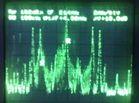
Image of Frequency Spectrum

Information

Ref = 102dBμ

BW = 100 KHz

CF = 5 MHz

CP1ΔF + 4.32 MHz

2 MHz / DIV

ΔV + 18.8 dB

Image Carrier Frequency:

LSB = 5 MHz - 4.32 MHz

USB = 5 MHz + 4.32 MHz

Voice carrier frequency: can not be detected by the frequency spectrum analyzer because it's frequency very small

Ref = 102dBμ

BW = 100 KHz

CF = 214 MHz

CP1ΔF + 4.32 MHz

2 MHz / DIV

ΔV + 18.8 dB

Image Carrier Frequency

LSB = 214 MHz - 4.32 MHz

USB = 214 MHz + 4.32 MHz

Voice carrier frequency: can not be seen by the spectrum analyzer because it's frequency very small

Ref = 102dBμ

BW = 100 KHz

CF = 421 MHz

CP1ΔF + 4.32 MHz

2 MHz / DIV

ΔV + 18.8 dB

Image carrier frequency:

LSB = 421 MHz - 4.32 MHz

USB = 421 MHz + 4.32 MHz

Voice carrier frequency: can not be seen by the spectrum analyzer because it's frequency very small


Ref = 102dBμ

BW = 100 KHz

CF = 624 MHz

CP1ΔF + 4.32 MHz

2 MHz / DIV

ΔV + 18.8 dB

Image Carrier Frequency:

LSB = 624 MHz - 4,32 MHz

USB= 624 MHz + 4,32 MHz

Voice carrier frequency: can not be seen by the spectrum analyzer because it's frequency very small

Ref = 102dBμ

BW = 100 KHz

CF = 831 MHz

CP1ΔF + 4.32 MHz

2 MHz / DIV

ΔV + 18.8 dB

Image Carrier Frequency:

LSB = 831 MHz - 4.32 MHz

USB = 831 MHz + 4.32 MHz

Voice carrier frequency: can not be seen by the spectrum analyzer because it's frequency very small


Ref = 102dBμ

BW = 100 KHz

CF = 1055 MHz

CP1ΔF + 4.32 MHz

2 MHz / DIV

ΔV + 18.8 dB

Image Carrier Frequency:

LSB = 1055 MHz - 4.32 MHz

USB = 1055 MHz + 4.32 MHz

Voice carrier frequency: can not be seen by the spectrum analyzer because it's frequency very small


DATA ANALYSIS:

From the spectrum image that we get, we can know that the value of:

Carrier frequency: 421 MHz

CP1ΔF + 4.32 MHz

Then:

USB = 421 MHz + 4.32 MHz = 425.32 MHz

LSB = 421 MHz - 4.32 MHz = 416.68 MHz

Voice carrier frequency: can not be seen by the spectrum analyzer because it's frequency very smaller than the frequency carrier.

For the multiples frequencies:

  • 1st multiple : 5 MHz
  • 2nd multiple : 214 MHz
  • 3rd multiples : 624 MHz
  • 4th multiples : 813 MHz
  • 5th multiples : 1055 MHz
The sound signal is separate and is transmitted at the upper edge of this signal but in this experiment it cannot be seen clearly. Carrier is shifted to bandpass and increase the one side bandwidth.

Unlike voice signals which have no components near the zero frequency, Video signals are very sensitive to their low frequency content. Distortion in these components degrades the picture. So extra care has to be taken to make sure that all the low frequency components (which are located in the center) are transmitted without distortion.

QUESTION'S ANSWER:

  1. Modulation system that being use in the video are AMPLITUDE MODULATION, because the signal amplitude information affect the amplitude of the carrier signal, the signal information into the cover of the carrier signal.


Image Modulated Signal

A common use of signal Am is: AM radio broadcasting is widely used for broadcast AM radio wave signal, the TV image (Video), Radio communication: aircraft, amateur radio (SSB), CB radio (Citizens Band Radio). Digital data transmission: Modems Computers (combined with QAM modulation)

  1. This type of modulation is amplitude modulation and it can be seen from the changes in amplitude and has a spectrum of AM.

Based on the equation of the spectrum signal AM modulated, AM will have 3 (three frequencies):

  • fc: carrier frequency signal
  • LSB: Lower Side Band frequency (LSB), namely the difference between frequency carrier signal and the signal information.
  • USB: Upper Side Band frequency (USB) is the addition of carrier signal frequency and signal information.


CONCLUSION

  1. Video modulator is using amplitude modulation (AM)
  2. AM modulation that shown on a spectrum analyzer displays are three frequencies namely
  • Carrier frequency (fc)
  • Lower Side Band Frequency (LSB)
  • Upper Side Band Frequency (USB)
  1. The difference between USB and LSB frequencies are = 4.32 MHz
  2. Using 100 KHz bandwidth


Reference

http://en.wikipedia.org/wiki/Amplitude_modulation

http://elkakom.telkompoltek.net/

http://vodpod.com/watch/1793578-lecture-8-amplitude-modulation

http://www.complextoreal.com/base.htm